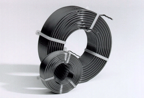
Solen Inc. was the first inductor design company to introduce the perfect lay hexagonal winding technique to manufacture inductors and to apply it to the design of a complete line of air cored inductors for the loudspeaker industry. Engineering efforts in component quality, lower resistance and specially tight tolerance have yielded the succesful development of the Perfect Lay Hexagonal Winding Air Cored Inductors.
As opposed to standard machine wound which produce non precision random or square type loose winding, high precision perfect lay hexagonal winding technique has several advantages over the machine wound type. The following describes several engineering developments that were incorporated in the design of the Perfect Lay Hexagonal Winding Air Cored Inductors to improve the quality factor, to lower the d. c. resistance, to linearized the a. c. resistance, to lower the magnetostriction and to better tolerance.
Wheeler Formula
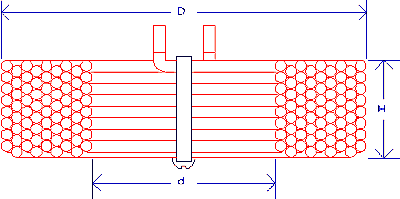
The Wheeler Formula for multi layer air cored inductor was used and integrated in a computer program and it was utilized to efficiently evaluate each air cored inductor design for optimum size and lowest d.c. resistance for any given inductance and wire size. After the most promising designs were identified, they were merged and incorporated to give a series of 12 different computer optimized air cored inductor dimensions (L x d x D) that cover the whole range of the inductance values and wire size ranges.
Perfect Layer Winder
Sophisticated, state of the art, perfect layer winding equipment along with a complete set of 12 proprietary high precision winding toolings were custom designed, developed and manufactured by Solen in order to be able to produce the highest quality and the most complete line of self supporting perfect layer hexagonal winding air cored inductors available today.
Hexagonal Winding
High precision winding tooling is the only way to achieve perfect lay hexagonal winding technique that make each turn to be winded side by side for each layer and each turn of subsequent layer is alternatively offset from the lower layer turn by a distance equal to the radius of the wire used. This produce an extremely tight honeycomb structured winding area multi layer self supporting air cored inductor which will provide the best possible winding space factor for any given inductor.
Magnetostriction effect
The tight honeycomb structured winding cut most of the non linear magnetostriction losses via acoustic radiation which is a distortion produced by the mechanical vibration of each turn of wire induced by the alternating magnetic field resulting from the alternating current passing into the inductor.
All those factors combine to give an superior inductor with the best possible specifications: a higher quality factor, lower d. c. resistance, more linear a. c. resistance, lower magnetostriction losses, closer tolerance, lower stray capacitance, longer stability and the best sonic quality for any given value of inductor. They are the NEC PLUS ULTRA of todays inductors because they were originally designed has a cost no object project and has a no compromise achievement.
Solen 2004
 DC Resistance (Ohms) +5%
Dimensions (mm) +10%
S14 1.63 mm Ø / 14 AWG
P/N Inductance/DCR LxdxD
-----------------------------
S14.16 .16 mH .07 14x29x57
S14.18 .18 mH .08 14x29x57
S14.20 .20 mH .08 14x29x57
S14.22 .22 mH .09 14x29x57
S14.27 .27 mH .10 14x29x57
S14.33 .33 mH .11 16x32x64
S14.39 .39 mH .12 16x32x64
S14.47 .47 mH .13 16x32x64
S14.51 .51 mH .14 16x32x64
S14.56 .56 mH .15 16x32x64
S14.68 .68 mH .17 19x38x76
S14.82 .82 mH .19 19x38x76
S141.0 1.0 mH .21 19x38x76
S141.2 1.2 mH .24 19x38x76
S141.5 1.5 mH .28 19x38x76
S141.8 1.8 mH .30 22x45x89
S142.2 2.2 mH .33 22x45x89
S142.7 2.7 mH .39 22x45x89
S143.0 3.0 mH .42 22x45x89
S143.3 3.3 mH .45 25x51x102
S143.9 3.9 mH .49 25x51x102
S144.7 4.7 mH .56 25x51x102
S145.1 5.1 mH .59 25x51x102
S145.6 5.6 mH .63 25x51x102
S146.8 6.8 mH .71 32x64x127
S148.2 8.2 mH .79 32x64x127
S1410 10 mH .87 32x64x127
Maximum d. c. resistance for series inductors for 8 ohms load: 0.6 Ohms total.
Maximum d. c. resistance for parallel inductors for 8 ohms load: 1.2 Ohms.
